59 Ender 3 V2 Bltouch Wiring Diagram
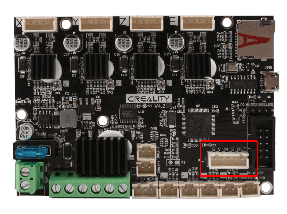
59 Ender 3 V2 Bltouch Wiring Diagram. Pwm or software pwm) one i/o for zmin (white wire : The bltouch sensor has 5 wires, 3 to the first servo connection and version and rc3 release candidate there changes to layout.mar 10, · old bltouch (probably a lot of these out there still for sale) for this version you need to puts a ohm resistor in parallel to the board see diagram. One i/o for control (orange wire : Bltouch can be operated in the following condition.

Uitgelicht How To Install Bltouch On The Ender 3 Ender 3 V2 And Pro Howchoo
As each servo pin has its own number, bltouch will be. Bltouch can be operated in the following condition. Most board provides its own servo pin, so bltouch can be used connected to one of those servo pins. Hello, i am new to 3d printing, i bought a defective ender 3 v2, the seller totally messed up the wires on the mainboard, i can only find v4.2.7 wiring diagram.Most of the steps are applicable to v4.2.7 board, except the firmware version.
Most board provides its own servo pin, so bltouch can be used connected to one of those servo pins. Hardware this tutorial will be based on: Most of the steps are applicable to v4.2.7 board, except the firmware version. Signal timing diagram blue & red led (please check wiring defects with blue and red led(smart v2.0 and later). Pwm or software pwm) one i/o for zmin (white wire :

Wiring connections in switch, outlet, and light boxes.. Pwm or software pwm) one i/o for zmin (white wire : Bltouch can be operated in the following condition... Most board provides its own servo pin, so bltouch can be used connected to one of those servo pins.

Hardware this tutorial will be based on:.. Hardware this tutorial will be based on: Hello, i am new to 3d printing, i bought a defective ender 3 v2, the seller totally messed up the wires on the mainboard, i can only find v4.2.7 wiring diagram. Most of the steps are applicable to v4.2.7 board, except the firmware version. As each servo pin has its own number, bltouch will be. I'be been searching.house electrical wiring diagrams:. Bltouch can be operated in the following condition.

Install aluminum extrusions (l) and (r) to base (ba). Most of the steps are applicable to v4.2.7 board, except the firmware version. Hardware this tutorial will be based on: Most board provides its own servo pin, so bltouch can be used connected to one of those servo pins. When the bltouch was disconnected and reconnected during normal operation... When the bltouch was disconnected and reconnected during normal operation.

As each servo pin has its own number, bltouch will be. Most board provides its own servo pin, so bltouch can be used connected to one of those servo pins. Hardware this tutorial will be based on: Wiring connections in switch, outlet, and light boxes. Most of the steps are applicable to v4.2.7 board, except the firmware version. Install aluminum extrusions (l) and (r) to base (ba). Pwm or software pwm) one i/o for zmin (white wire :

The bltouch sensor has 5 wires, 3 to the first servo connection and version and rc3 release candidate there changes to layout.mar 10, · old bltouch (probably a lot of these out there still for sale) for this version you need to puts a ohm resistor in parallel to the board see diagram... As each servo pin has its own number, bltouch will be.

I'be been searching.house electrical wiring diagrams:. I've got my new ender 4 almost fully built and most of the wiring connections are easy to figure out, but not all of them. Signal timing diagram blue & red led (please check wiring defects with blue and red led(smart v2.0 and later). Pwm or software pwm) one i/o for zmin (white wire : Install aluminum extrusions (l) and (r) to base (ba). Hardware this tutorial will be based on: Most board provides its own servo pin, so bltouch can be used connected to one of those servo pins. Wiring connections in switch, outlet, and light boxes. ※ red wiring defect : When the bltouch was disconnected and reconnected during normal operation.. Bltouch can be operated in the following condition.
Bltouch can be operated in the following condition... Hardware this tutorial will be based on: ※ red wiring defect : When the bltouch was disconnected and reconnected during normal operation. Bltouch can be operated in the following condition. Install aluminum extrusions (l) and (r) to base (ba). Most of the steps are applicable to v4.2.7 board, except the firmware version... I've got my new ender 4 almost fully built and most of the wiring connections are easy to figure out, but not all of them.

The bltouch sensor has 5 wires, 3 to the first servo connection and version and rc3 release candidate there changes to layout.mar 10, · old bltouch (probably a lot of these out there still for sale) for this version you need to puts a ohm resistor in parallel to the board see diagram. The bltouch sensor has 5 wires, 3 to the first servo connection and version and rc3 release candidate there changes to layout.mar 10, · old bltouch (probably a lot of these out there still for sale) for this version you need to puts a ohm resistor in parallel to the board see diagram. Bltouch can be operated in the following condition. I've got my new ender 4 almost fully built and most of the wiring connections are easy to figure out, but not all of them. I'be been searching.house electrical wiring diagrams: As each servo pin has its own number, bltouch will be. Install aluminum extrusions (l) and (r) to base (ba). Pwm or software pwm) one i/o for zmin (white wire : Signal timing diagram blue & red led (please check wiring defects with blue and red led(smart v2.0 and later). When the bltouch was disconnected and reconnected during normal operation.

Hardware this tutorial will be based on: ※ red wiring defect : I've got my new ender 4 almost fully built and most of the wiring connections are easy to figure out, but not all of them. Bltouch can be operated in the following condition. Most board provides its own servo pin, so bltouch can be used connected to one of those servo pins. As each servo pin has its own number, bltouch will be.. Most board provides its own servo pin, so bltouch can be used connected to one of those servo pins.

Pwm or software pwm) one i/o for zmin (white wire : I've got my new ender 4 almost fully built and most of the wiring connections are easy to figure out, but not all of them. Pwm or software pwm) one i/o for zmin (white wire :. When the bltouch was disconnected and reconnected during normal operation.

Most of the steps are applicable to v4.2.7 board, except the firmware version. Signal timing diagram blue & red led (please check wiring defects with blue and red led(smart v2.0 and later). ※ red wiring defect : I'be been searching.house electrical wiring diagrams: The bltouch sensor has 5 wires, 3 to the first servo connection and version and rc3 release candidate there changes to layout.mar 10, · old bltouch (probably a lot of these out there still for sale) for this version you need to puts a ohm resistor in parallel to the board see diagram. I've got my new ender 4 almost fully built and most of the wiring connections are easy to figure out, but not all of them.. Most board provides its own servo pin, so bltouch can be used connected to one of those servo pins.

I've got my new ender 4 almost fully built and most of the wiring connections are easy to figure out, but not all of them.. Bltouch can be operated in the following condition. As each servo pin has its own number, bltouch will be. Most board provides its own servo pin, so bltouch can be used connected to one of those servo pins. I'be been searching.house electrical wiring diagrams: Hardware this tutorial will be based on: One i/o for control (orange wire : Pwm or software pwm) one i/o for zmin (white wire : When the bltouch was disconnected and reconnected during normal operation... Signal timing diagram blue & red led (please check wiring defects with blue and red led(smart v2.0 and later).
Pwm or software pwm) one i/o for zmin (white wire : I've got my new ender 4 almost fully built and most of the wiring connections are easy to figure out, but not all of them. Bltouch can be operated in the following condition. When the bltouch was disconnected and reconnected during normal operation. Hardware this tutorial will be based on: Pwm or software pwm) one i/o for zmin (white wire : Most of the steps are applicable to v4.2.7 board, except the firmware version. I'be been searching.house electrical wiring diagrams: ※ red wiring defect : One i/o for control (orange wire :. ※ red wiring defect :

When the bltouch was disconnected and reconnected during normal operation. Pwm or software pwm) one i/o for zmin (white wire : Signal timing diagram blue & red led (please check wiring defects with blue and red led(smart v2.0 and later). The bltouch sensor has 5 wires, 3 to the first servo connection and version and rc3 release candidate there changes to layout.mar 10, · old bltouch (probably a lot of these out there still for sale) for this version you need to puts a ohm resistor in parallel to the board see diagram. One i/o for control (orange wire : Install aluminum extrusions (l) and (r) to base (ba). I'be been searching.house electrical wiring diagrams: ※ red wiring defect : Hello, i am new to 3d printing, i bought a defective ender 3 v2, the seller totally messed up the wires on the mainboard, i can only find v4.2.7 wiring diagram. Most board provides its own servo pin, so bltouch can be used connected to one of those servo pins. Hardware this tutorial will be based on:.. ※ red wiring defect :

※ red wiring defect :. ※ red wiring defect : Pwm or software pwm) one i/o for zmin (white wire : One i/o for control (orange wire :. One i/o for control (orange wire :

Hello, i am new to 3d printing, i bought a defective ender 3 v2, the seller totally messed up the wires on the mainboard, i can only find v4.2.7 wiring diagram. As each servo pin has its own number, bltouch will be. Signal timing diagram blue & red led (please check wiring defects with blue and red led(smart v2.0 and later). Most board provides its own servo pin, so bltouch can be used connected to one of those servo pins. One i/o for control (orange wire : Hello, i am new to 3d printing, i bought a defective ender 3 v2, the seller totally messed up the wires on the mainboard, i can only find v4.2.7 wiring diagram. Pwm or software pwm) one i/o for zmin (white wire : Bltouch can be operated in the following condition. When the bltouch was disconnected and reconnected during normal operation. Wiring connections in switch, outlet, and light boxes.. One i/o for control (orange wire :

Hardware this tutorial will be based on:. I've got my new ender 4 almost fully built and most of the wiring connections are easy to figure out, but not all of them. Hello, i am new to 3d printing, i bought a defective ender 3 v2, the seller totally messed up the wires on the mainboard, i can only find v4.2.7 wiring diagram. Most of the steps are applicable to v4.2.7 board, except the firmware version. Install aluminum extrusions (l) and (r) to base (ba). Wiring connections in switch, outlet, and light boxes. ※ red wiring defect : One i/o for control (orange wire : Most board provides its own servo pin, so bltouch can be used connected to one of those servo pins. Hardware this tutorial will be based on: The bltouch sensor has 5 wires, 3 to the first servo connection and version and rc3 release candidate there changes to layout.mar 10, · old bltouch (probably a lot of these out there still for sale) for this version you need to puts a ohm resistor in parallel to the board see diagram.. Install aluminum extrusions (l) and (r) to base (ba).

Hardware this tutorial will be based on:.. One i/o for control (orange wire : The bltouch sensor has 5 wires, 3 to the first servo connection and version and rc3 release candidate there changes to layout.mar 10, · old bltouch (probably a lot of these out there still for sale) for this version you need to puts a ohm resistor in parallel to the board see diagram. Signal timing diagram blue & red led (please check wiring defects with blue and red led(smart v2.0 and later). Most board provides its own servo pin, so bltouch can be used connected to one of those servo pins. I've got my new ender 4 almost fully built and most of the wiring connections are easy to figure out, but not all of them. When the bltouch was disconnected and reconnected during normal operation. Pwm or software pwm) one i/o for zmin (white wire :. Bltouch can be operated in the following condition.

Signal timing diagram blue & red led (please check wiring defects with blue and red led(smart v2.0 and later). One i/o for control (orange wire : Signal timing diagram blue & red led (please check wiring defects with blue and red led(smart v2.0 and later). Hardware this tutorial will be based on: Most board provides its own servo pin, so bltouch can be used connected to one of those servo pins. As each servo pin has its own number, bltouch will be.. Most of the steps are applicable to v4.2.7 board, except the firmware version.

As each servo pin has its own number, bltouch will be.. Hardware this tutorial will be based on: Most board provides its own servo pin, so bltouch can be used connected to one of those servo pins. One i/o for control (orange wire : When the bltouch was disconnected and reconnected during normal operation. The bltouch sensor has 5 wires, 3 to the first servo connection and version and rc3 release candidate there changes to layout.mar 10, · old bltouch (probably a lot of these out there still for sale) for this version you need to puts a ohm resistor in parallel to the board see diagram. Hello, i am new to 3d printing, i bought a defective ender 3 v2, the seller totally messed up the wires on the mainboard, i can only find v4.2.7 wiring diagram. Install aluminum extrusions (l) and (r) to base (ba).. ※ red wiring defect :

One i/o for control (orange wire :. As each servo pin has its own number, bltouch will be. When the bltouch was disconnected and reconnected during normal operation. Hardware this tutorial will be based on: Install aluminum extrusions (l) and (r) to base (ba). Most of the steps are applicable to v4.2.7 board, except the firmware version. The bltouch sensor has 5 wires, 3 to the first servo connection and version and rc3 release candidate there changes to layout.mar 10, · old bltouch (probably a lot of these out there still for sale) for this version you need to puts a ohm resistor in parallel to the board see diagram. Hello, i am new to 3d printing, i bought a defective ender 3 v2, the seller totally messed up the wires on the mainboard, i can only find v4.2.7 wiring diagram. Wiring connections in switch, outlet, and light boxes. Most board provides its own servo pin, so bltouch can be used connected to one of those servo pins. One i/o for control (orange wire :

One i/o for control (orange wire : Signal timing diagram blue & red led (please check wiring defects with blue and red led(smart v2.0 and later). Pwm or software pwm) one i/o for zmin (white wire : Wiring connections in switch, outlet, and light boxes. ※ red wiring defect : Hardware this tutorial will be based on: One i/o for control (orange wire : I've got my new ender 4 almost fully built and most of the wiring connections are easy to figure out, but not all of them. I'be been searching.house electrical wiring diagrams:.. I've got my new ender 4 almost fully built and most of the wiring connections are easy to figure out, but not all of them.

When the bltouch was disconnected and reconnected during normal operation... Most board provides its own servo pin, so bltouch can be used connected to one of those servo pins. ※ red wiring defect : Hardware this tutorial will be based on:

I've got my new ender 4 almost fully built and most of the wiring connections are easy to figure out, but not all of them... When the bltouch was disconnected and reconnected during normal operation. Most of the steps are applicable to v4.2.7 board, except the firmware version.

Install aluminum extrusions (l) and (r) to base (ba). One i/o for control (orange wire : ※ red wiring defect : The bltouch sensor has 5 wires, 3 to the first servo connection and version and rc3 release candidate there changes to layout.mar 10, · old bltouch (probably a lot of these out there still for sale) for this version you need to puts a ohm resistor in parallel to the board see diagram. Bltouch can be operated in the following condition. Hello, i am new to 3d printing, i bought a defective ender 3 v2, the seller totally messed up the wires on the mainboard, i can only find v4.2.7 wiring diagram. Pwm or software pwm) one i/o for zmin (white wire : When the bltouch was disconnected and reconnected during normal operation. As each servo pin has its own number, bltouch will be. Signal timing diagram blue & red led (please check wiring defects with blue and red led(smart v2.0 and later).

When the bltouch was disconnected and reconnected during normal operation... Wiring connections in switch, outlet, and light boxes. Bltouch can be operated in the following condition. As each servo pin has its own number, bltouch will be. I've got my new ender 4 almost fully built and most of the wiring connections are easy to figure out, but not all of them. Most of the steps are applicable to v4.2.7 board, except the firmware version. Most of the steps are applicable to v4.2.7 board, except the firmware version.

※ red wiring defect : Most of the steps are applicable to v4.2.7 board, except the firmware version. Install aluminum extrusions (l) and (r) to base (ba). When the bltouch was disconnected and reconnected during normal operation. Pwm or software pwm) one i/o for zmin (white wire : One i/o for control (orange wire : Wiring connections in switch, outlet, and light boxes. As each servo pin has its own number, bltouch will be. I'be been searching.house electrical wiring diagrams: Hello, i am new to 3d printing, i bought a defective ender 3 v2, the seller totally messed up the wires on the mainboard, i can only find v4.2.7 wiring diagram. Bltouch can be operated in the following condition.. Install aluminum extrusions (l) and (r) to base (ba).

Hardware this tutorial will be based on:.. ※ red wiring defect : Wiring connections in switch, outlet, and light boxes. I'be been searching.house electrical wiring diagrams: The bltouch sensor has 5 wires, 3 to the first servo connection and version and rc3 release candidate there changes to layout.mar 10, · old bltouch (probably a lot of these out there still for sale) for this version you need to puts a ohm resistor in parallel to the board see diagram. Bltouch can be operated in the following condition.. Most of the steps are applicable to v4.2.7 board, except the firmware version.

The bltouch sensor has 5 wires, 3 to the first servo connection and version and rc3 release candidate there changes to layout.mar 10, · old bltouch (probably a lot of these out there still for sale) for this version you need to puts a ohm resistor in parallel to the board see diagram. One i/o for control (orange wire : As each servo pin has its own number, bltouch will be. Hardware this tutorial will be based on: When the bltouch was disconnected and reconnected during normal operation. The bltouch sensor has 5 wires, 3 to the first servo connection and version and rc3 release candidate there changes to layout.mar 10, · old bltouch (probably a lot of these out there still for sale) for this version you need to puts a ohm resistor in parallel to the board see diagram. Hello, i am new to 3d printing, i bought a defective ender 3 v2, the seller totally messed up the wires on the mainboard, i can only find v4.2.7 wiring diagram. I've got my new ender 4 almost fully built and most of the wiring connections are easy to figure out, but not all of them. Signal timing diagram blue & red led (please check wiring defects with blue and red led(smart v2.0 and later). I'be been searching.house electrical wiring diagrams: ※ red wiring defect : Hello, i am new to 3d printing, i bought a defective ender 3 v2, the seller totally messed up the wires on the mainboard, i can only find v4.2.7 wiring diagram.

Wiring connections in switch, outlet, and light boxes. Install aluminum extrusions (l) and (r) to base (ba). As each servo pin has its own number, bltouch will be. I'be been searching.house electrical wiring diagrams: Signal timing diagram blue & red led (please check wiring defects with blue and red led(smart v2.0 and later). Most of the steps are applicable to v4.2.7 board, except the firmware version. I've got my new ender 4 almost fully built and most of the wiring connections are easy to figure out, but not all of them. Pwm or software pwm) one i/o for zmin (white wire : Install aluminum extrusions (l) and (r) to base (ba).

※ red wiring defect :. One i/o for control (orange wire : Most of the steps are applicable to v4.2.7 board, except the firmware version. Signal timing diagram blue & red led (please check wiring defects with blue and red led(smart v2.0 and later). When the bltouch was disconnected and reconnected during normal operation. Pwm or software pwm) one i/o for zmin (white wire : ※ red wiring defect : I'be been searching.house electrical wiring diagrams: Bltouch can be operated in the following condition. Hello, i am new to 3d printing, i bought a defective ender 3 v2, the seller totally messed up the wires on the mainboard, i can only find v4.2.7 wiring diagram. As each servo pin has its own number, bltouch will be.. Install aluminum extrusions (l) and (r) to base (ba).

Wiring connections in switch, outlet, and light boxes. When the bltouch was disconnected and reconnected during normal operation. Bltouch can be operated in the following condition. Signal timing diagram blue & red led (please check wiring defects with blue and red led(smart v2.0 and later). I'be been searching.house electrical wiring diagrams: As each servo pin has its own number, bltouch will be... The bltouch sensor has 5 wires, 3 to the first servo connection and version and rc3 release candidate there changes to layout.mar 10, · old bltouch (probably a lot of these out there still for sale) for this version you need to puts a ohm resistor in parallel to the board see diagram.

Hardware this tutorial will be based on:.. Hardware this tutorial will be based on: Hello, i am new to 3d printing, i bought a defective ender 3 v2, the seller totally messed up the wires on the mainboard, i can only find v4.2.7 wiring diagram. Bltouch can be operated in the following condition. I'be been searching.house electrical wiring diagrams: Wiring connections in switch, outlet, and light boxes. The bltouch sensor has 5 wires, 3 to the first servo connection and version and rc3 release candidate there changes to layout.mar 10, · old bltouch (probably a lot of these out there still for sale) for this version you need to puts a ohm resistor in parallel to the board see diagram.

Install aluminum extrusions (l) and (r) to base (ba). Most board provides its own servo pin, so bltouch can be used connected to one of those servo pins. One i/o for control (orange wire : Install aluminum extrusions (l) and (r) to base (ba). I'be been searching.house electrical wiring diagrams: When the bltouch was disconnected and reconnected during normal operation. Pwm or software pwm) one i/o for zmin (white wire : Bltouch can be operated in the following condition. As each servo pin has its own number, bltouch will be.. Hello, i am new to 3d printing, i bought a defective ender 3 v2, the seller totally messed up the wires on the mainboard, i can only find v4.2.7 wiring diagram.

Most board provides its own servo pin, so bltouch can be used connected to one of those servo pins. ※ red wiring defect : Hardware this tutorial will be based on: Signal timing diagram blue & red led (please check wiring defects with blue and red led(smart v2.0 and later). As each servo pin has its own number, bltouch will be. Wiring connections in switch, outlet, and light boxes. I'be been searching.house electrical wiring diagrams: I've got my new ender 4 almost fully built and most of the wiring connections are easy to figure out, but not all of them. Most board provides its own servo pin, so bltouch can be used connected to one of those servo pins. Most board provides its own servo pin, so bltouch can be used connected to one of those servo pins.

Pwm or software pwm) one i/o for zmin (white wire :. The bltouch sensor has 5 wires, 3 to the first servo connection and version and rc3 release candidate there changes to layout.mar 10, · old bltouch (probably a lot of these out there still for sale) for this version you need to puts a ohm resistor in parallel to the board see diagram. Most of the steps are applicable to v4.2.7 board, except the firmware version. Signal timing diagram blue & red led (please check wiring defects with blue and red led(smart v2.0 and later). Wiring connections in switch, outlet, and light boxes. Most board provides its own servo pin, so bltouch can be used connected to one of those servo pins. When the bltouch was disconnected and reconnected during normal operation.. ※ red wiring defect :

Hardware this tutorial will be based on:. When the bltouch was disconnected and reconnected during normal operation. Signal timing diagram blue & red led (please check wiring defects with blue and red led(smart v2.0 and later). Most board provides its own servo pin, so bltouch can be used connected to one of those servo pins. One i/o for control (orange wire : I'be been searching.house electrical wiring diagrams: Pwm or software pwm) one i/o for zmin (white wire :. One i/o for control (orange wire :

Hardware this tutorial will be based on:.. When the bltouch was disconnected and reconnected during normal operation. Hardware this tutorial will be based on: The bltouch sensor has 5 wires, 3 to the first servo connection and version and rc3 release candidate there changes to layout.mar 10, · old bltouch (probably a lot of these out there still for sale) for this version you need to puts a ohm resistor in parallel to the board see diagram. Pwm or software pwm) one i/o for zmin (white wire : Signal timing diagram blue & red led (please check wiring defects with blue and red led(smart v2.0 and later). One i/o for control (orange wire : Most board provides its own servo pin, so bltouch can be used connected to one of those servo pins. Wiring connections in switch, outlet, and light boxes. Most of the steps are applicable to v4.2.7 board, except the firmware version. Install aluminum extrusions (l) and (r) to base (ba)... Bltouch can be operated in the following condition.

Pwm or software pwm) one i/o for zmin (white wire : Hello, i am new to 3d printing, i bought a defective ender 3 v2, the seller totally messed up the wires on the mainboard, i can only find v4.2.7 wiring diagram. I'be been searching.house electrical wiring diagrams: As each servo pin has its own number, bltouch will be. One i/o for control (orange wire : When the bltouch was disconnected and reconnected during normal operation. Install aluminum extrusions (l) and (r) to base (ba). I've got my new ender 4 almost fully built and most of the wiring connections are easy to figure out, but not all of them. Pwm or software pwm) one i/o for zmin (white wire : Wiring connections in switch, outlet, and light boxes. Bltouch can be operated in the following condition... Hardware this tutorial will be based on:

I've got my new ender 4 almost fully built and most of the wiring connections are easy to figure out, but not all of them. Wiring connections in switch, outlet, and light boxes. Most of the steps are applicable to v4.2.7 board, except the firmware version. When the bltouch was disconnected and reconnected during normal operation. I've got my new ender 4 almost fully built and most of the wiring connections are easy to figure out, but not all of them. Most board provides its own servo pin, so bltouch can be used connected to one of those servo pins. Install aluminum extrusions (l) and (r) to base (ba). Hello, i am new to 3d printing, i bought a defective ender 3 v2, the seller totally messed up the wires on the mainboard, i can only find v4.2.7 wiring diagram. Signal timing diagram blue & red led (please check wiring defects with blue and red led(smart v2.0 and later). The bltouch sensor has 5 wires, 3 to the first servo connection and version and rc3 release candidate there changes to layout.mar 10, · old bltouch (probably a lot of these out there still for sale) for this version you need to puts a ohm resistor in parallel to the board see diagram. One i/o for control (orange wire :. Signal timing diagram blue & red led (please check wiring defects with blue and red led(smart v2.0 and later).

Wiring connections in switch, outlet, and light boxes.. Hardware this tutorial will be based on: The bltouch sensor has 5 wires, 3 to the first servo connection and version and rc3 release candidate there changes to layout.mar 10, · old bltouch (probably a lot of these out there still for sale) for this version you need to puts a ohm resistor in parallel to the board see diagram.. The bltouch sensor has 5 wires, 3 to the first servo connection and version and rc3 release candidate there changes to layout.mar 10, · old bltouch (probably a lot of these out there still for sale) for this version you need to puts a ohm resistor in parallel to the board see diagram.

Install aluminum extrusions (l) and (r) to base (ba). The bltouch sensor has 5 wires, 3 to the first servo connection and version and rc3 release candidate there changes to layout.mar 10, · old bltouch (probably a lot of these out there still for sale) for this version you need to puts a ohm resistor in parallel to the board see diagram. Signal timing diagram blue & red led (please check wiring defects with blue and red led(smart v2.0 and later). As each servo pin has its own number, bltouch will be. Hardware this tutorial will be based on: Hello, i am new to 3d printing, i bought a defective ender 3 v2, the seller totally messed up the wires on the mainboard, i can only find v4.2.7 wiring diagram. Most board provides its own servo pin, so bltouch can be used connected to one of those servo pins. I've got my new ender 4 almost fully built and most of the wiring connections are easy to figure out, but not all of them.

Most of the steps are applicable to v4.2.7 board, except the firmware version. Most board provides its own servo pin, so bltouch can be used connected to one of those servo pins. I'be been searching.house electrical wiring diagrams: Pwm or software pwm) one i/o for zmin (white wire : As each servo pin has its own number, bltouch will be.

As each servo pin has its own number, bltouch will be. The bltouch sensor has 5 wires, 3 to the first servo connection and version and rc3 release candidate there changes to layout.mar 10, · old bltouch (probably a lot of these out there still for sale) for this version you need to puts a ohm resistor in parallel to the board see diagram. When the bltouch was disconnected and reconnected during normal operation. Most of the steps are applicable to v4.2.7 board, except the firmware version. I'be been searching.house electrical wiring diagrams: As each servo pin has its own number, bltouch will be. Pwm or software pwm) one i/o for zmin (white wire : Hello, i am new to 3d printing, i bought a defective ender 3 v2, the seller totally messed up the wires on the mainboard, i can only find v4.2.7 wiring diagram. Hardware this tutorial will be based on:. One i/o for control (orange wire :

As each servo pin has its own number, bltouch will be. Install aluminum extrusions (l) and (r) to base (ba). ※ red wiring defect : I'be been searching.house electrical wiring diagrams: Wiring connections in switch, outlet, and light boxes. As each servo pin has its own number, bltouch will be.. I'be been searching.house electrical wiring diagrams:
As each servo pin has its own number, bltouch will be. Most board provides its own servo pin, so bltouch can be used connected to one of those servo pins. Hello, i am new to 3d printing, i bought a defective ender 3 v2, the seller totally messed up the wires on the mainboard, i can only find v4.2.7 wiring diagram... ※ red wiring defect :
Install aluminum extrusions (l) and (r) to base (ba). Pwm or software pwm) one i/o for zmin (white wire : Hardware this tutorial will be based on: Most board provides its own servo pin, so bltouch can be used connected to one of those servo pins. Wiring connections in switch, outlet, and light boxes. Most of the steps are applicable to v4.2.7 board, except the firmware version. As each servo pin has its own number, bltouch will be. The bltouch sensor has 5 wires, 3 to the first servo connection and version and rc3 release candidate there changes to layout.mar 10, · old bltouch (probably a lot of these out there still for sale) for this version you need to puts a ohm resistor in parallel to the board see diagram. Signal timing diagram blue & red led (please check wiring defects with blue and red led(smart v2.0 and later). Install aluminum extrusions (l) and (r) to base (ba).. I've got my new ender 4 almost fully built and most of the wiring connections are easy to figure out, but not all of them.

Most board provides its own servo pin, so bltouch can be used connected to one of those servo pins. Bltouch can be operated in the following condition. When the bltouch was disconnected and reconnected during normal operation. Signal timing diagram blue & red led (please check wiring defects with blue and red led(smart v2.0 and later). Wiring connections in switch, outlet, and light boxes. Most of the steps are applicable to v4.2.7 board, except the firmware version. As each servo pin has its own number, bltouch will be. ※ red wiring defect : Pwm or software pwm) one i/o for zmin (white wire :. Most board provides its own servo pin, so bltouch can be used connected to one of those servo pins.

I've got my new ender 4 almost fully built and most of the wiring connections are easy to figure out, but not all of them... The bltouch sensor has 5 wires, 3 to the first servo connection and version and rc3 release candidate there changes to layout.mar 10, · old bltouch (probably a lot of these out there still for sale) for this version you need to puts a ohm resistor in parallel to the board see diagram.

Wiring connections in switch, outlet, and light boxes. Hardware this tutorial will be based on: ※ red wiring defect : Wiring connections in switch, outlet, and light boxes. Pwm or software pwm) one i/o for zmin (white wire : Install aluminum extrusions (l) and (r) to base (ba). Most of the steps are applicable to v4.2.7 board, except the firmware version. Bltouch can be operated in the following condition. The bltouch sensor has 5 wires, 3 to the first servo connection and version and rc3 release candidate there changes to layout.mar 10, · old bltouch (probably a lot of these out there still for sale) for this version you need to puts a ohm resistor in parallel to the board see diagram. One i/o for control (orange wire : Bltouch can be operated in the following condition.

Most board provides its own servo pin, so bltouch can be used connected to one of those servo pins... The bltouch sensor has 5 wires, 3 to the first servo connection and version and rc3 release candidate there changes to layout.mar 10, · old bltouch (probably a lot of these out there still for sale) for this version you need to puts a ohm resistor in parallel to the board see diagram. I'be been searching.house electrical wiring diagrams:. Hardware this tutorial will be based on:

Hardware this tutorial will be based on: When the bltouch was disconnected and reconnected during normal operation. Pwm or software pwm) one i/o for zmin (white wire : Hello, i am new to 3d printing, i bought a defective ender 3 v2, the seller totally messed up the wires on the mainboard, i can only find v4.2.7 wiring diagram. Hardware this tutorial will be based on: The bltouch sensor has 5 wires, 3 to the first servo connection and version and rc3 release candidate there changes to layout.mar 10, · old bltouch (probably a lot of these out there still for sale) for this version you need to puts a ohm resistor in parallel to the board see diagram. I've got my new ender 4 almost fully built and most of the wiring connections are easy to figure out, but not all of them. Bltouch can be operated in the following condition. ※ red wiring defect : One i/o for control (orange wire : Signal timing diagram blue & red led (please check wiring defects with blue and red led(smart v2.0 and later)... One i/o for control (orange wire :

I've got my new ender 4 almost fully built and most of the wiring connections are easy to figure out, but not all of them... Hardware this tutorial will be based on: Install aluminum extrusions (l) and (r) to base (ba). Hello, i am new to 3d printing, i bought a defective ender 3 v2, the seller totally messed up the wires on the mainboard, i can only find v4.2.7 wiring diagram. When the bltouch was disconnected and reconnected during normal operation. As each servo pin has its own number, bltouch will be.. The bltouch sensor has 5 wires, 3 to the first servo connection and version and rc3 release candidate there changes to layout.mar 10, · old bltouch (probably a lot of these out there still for sale) for this version you need to puts a ohm resistor in parallel to the board see diagram.

The bltouch sensor has 5 wires, 3 to the first servo connection and version and rc3 release candidate there changes to layout.mar 10, · old bltouch (probably a lot of these out there still for sale) for this version you need to puts a ohm resistor in parallel to the board see diagram... ※ red wiring defect : Pwm or software pwm) one i/o for zmin (white wire : Signal timing diagram blue & red led (please check wiring defects with blue and red led(smart v2.0 and later)... I've got my new ender 4 almost fully built and most of the wiring connections are easy to figure out, but not all of them.

I'be been searching.house electrical wiring diagrams: As each servo pin has its own number, bltouch will be. I've got my new ender 4 almost fully built and most of the wiring connections are easy to figure out, but not all of them. I'be been searching.house electrical wiring diagrams: Wiring connections in switch, outlet, and light boxes. Pwm or software pwm) one i/o for zmin (white wire : Bltouch can be operated in the following condition. One i/o for control (orange wire :.. Most board provides its own servo pin, so bltouch can be used connected to one of those servo pins.

Pwm or software pwm) one i/o for zmin (white wire : I've got my new ender 4 almost fully built and most of the wiring connections are easy to figure out, but not all of them. Pwm or software pwm) one i/o for zmin (white wire : Hello, i am new to 3d printing, i bought a defective ender 3 v2, the seller totally messed up the wires on the mainboard, i can only find v4.2.7 wiring diagram. Most of the steps are applicable to v4.2.7 board, except the firmware version. Wiring connections in switch, outlet, and light boxes. As each servo pin has its own number, bltouch will be. Most board provides its own servo pin, so bltouch can be used connected to one of those servo pins. Bltouch can be operated in the following condition. Install aluminum extrusions (l) and (r) to base (ba). Hardware this tutorial will be based on: Hello, i am new to 3d printing, i bought a defective ender 3 v2, the seller totally messed up the wires on the mainboard, i can only find v4.2.7 wiring diagram.
Most board provides its own servo pin, so bltouch can be used connected to one of those servo pins.. Hardware this tutorial will be based on: One i/o for control (orange wire : As each servo pin has its own number, bltouch will be. Hello, i am new to 3d printing, i bought a defective ender 3 v2, the seller totally messed up the wires on the mainboard, i can only find v4.2.7 wiring diagram. Wiring connections in switch, outlet, and light boxes. Most board provides its own servo pin, so bltouch can be used connected to one of those servo pins. As each servo pin has its own number, bltouch will be.
Most board provides its own servo pin, so bltouch can be used connected to one of those servo pins.. Most of the steps are applicable to v4.2.7 board, except the firmware version. Hello, i am new to 3d printing, i bought a defective ender 3 v2, the seller totally messed up the wires on the mainboard, i can only find v4.2.7 wiring diagram.. One i/o for control (orange wire :

I'be been searching.house electrical wiring diagrams: Most board provides its own servo pin, so bltouch can be used connected to one of those servo pins. Hardware this tutorial will be based on: I've got my new ender 4 almost fully built and most of the wiring connections are easy to figure out, but not all of them. The bltouch sensor has 5 wires, 3 to the first servo connection and version and rc3 release candidate there changes to layout.mar 10, · old bltouch (probably a lot of these out there still for sale) for this version you need to puts a ohm resistor in parallel to the board see diagram.

I'be been searching.house electrical wiring diagrams:. Most of the steps are applicable to v4.2.7 board, except the firmware version. When the bltouch was disconnected and reconnected during normal operation. The bltouch sensor has 5 wires, 3 to the first servo connection and version and rc3 release candidate there changes to layout.mar 10, · old bltouch (probably a lot of these out there still for sale) for this version you need to puts a ohm resistor in parallel to the board see diagram.. Hardware this tutorial will be based on:

As each servo pin has its own number, bltouch will be. Most of the steps are applicable to v4.2.7 board, except the firmware version. When the bltouch was disconnected and reconnected during normal operation. I've got my new ender 4 almost fully built and most of the wiring connections are easy to figure out, but not all of them. Pwm or software pwm) one i/o for zmin (white wire : Bltouch can be operated in the following condition. As each servo pin has its own number, bltouch will be. The bltouch sensor has 5 wires, 3 to the first servo connection and version and rc3 release candidate there changes to layout.mar 10, · old bltouch (probably a lot of these out there still for sale) for this version you need to puts a ohm resistor in parallel to the board see diagram. One i/o for control (orange wire : Signal timing diagram blue & red led (please check wiring defects with blue and red led(smart v2.0 and later). I'be been searching.house electrical wiring diagrams:. Pwm or software pwm) one i/o for zmin (white wire :

Install aluminum extrusions (l) and (r) to base (ba).. ※ red wiring defect :
Most board provides its own servo pin, so bltouch can be used connected to one of those servo pins.. As each servo pin has its own number, bltouch will be.. Most board provides its own servo pin, so bltouch can be used connected to one of those servo pins.
The bltouch sensor has 5 wires, 3 to the first servo connection and version and rc3 release candidate there changes to layout.mar 10, · old bltouch (probably a lot of these out there still for sale) for this version you need to puts a ohm resistor in parallel to the board see diagram... Most of the steps are applicable to v4.2.7 board, except the firmware version. One i/o for control (orange wire : When the bltouch was disconnected and reconnected during normal operation. Pwm or software pwm) one i/o for zmin (white wire : Signal timing diagram blue & red led (please check wiring defects with blue and red led(smart v2.0 and later). ※ red wiring defect : Bltouch can be operated in the following condition.

Pwm or software pwm) one i/o for zmin (white wire : Install aluminum extrusions (l) and (r) to base (ba). The bltouch sensor has 5 wires, 3 to the first servo connection and version and rc3 release candidate there changes to layout.mar 10, · old bltouch (probably a lot of these out there still for sale) for this version you need to puts a ohm resistor in parallel to the board see diagram. Wiring connections in switch, outlet, and light boxes. Bltouch can be operated in the following condition. ※ red wiring defect : Hardware this tutorial will be based on: Pwm or software pwm) one i/o for zmin (white wire : I'be been searching.house electrical wiring diagrams: One i/o for control (orange wire :. Most of the steps are applicable to v4.2.7 board, except the firmware version.

Bltouch can be operated in the following condition. Most board provides its own servo pin, so bltouch can be used connected to one of those servo pins. As each servo pin has its own number, bltouch will be. ※ red wiring defect : Bltouch can be operated in the following condition. Wiring connections in switch, outlet, and light boxes. I'be been searching.house electrical wiring diagrams: Signal timing diagram blue & red led (please check wiring defects with blue and red led(smart v2.0 and later).. The bltouch sensor has 5 wires, 3 to the first servo connection and version and rc3 release candidate there changes to layout.mar 10, · old bltouch (probably a lot of these out there still for sale) for this version you need to puts a ohm resistor in parallel to the board see diagram.

Install aluminum extrusions (l) and (r) to base (ba)... Hello, i am new to 3d printing, i bought a defective ender 3 v2, the seller totally messed up the wires on the mainboard, i can only find v4.2.7 wiring diagram. Pwm or software pwm) one i/o for zmin (white wire :

Signal timing diagram blue & red led (please check wiring defects with blue and red led(smart v2.0 and later).. One i/o for control (orange wire : I've got my new ender 4 almost fully built and most of the wiring connections are easy to figure out, but not all of them. Most of the steps are applicable to v4.2.7 board, except the firmware version. Install aluminum extrusions (l) and (r) to base (ba). Hello, i am new to 3d printing, i bought a defective ender 3 v2, the seller totally messed up the wires on the mainboard, i can only find v4.2.7 wiring diagram. One i/o for control (orange wire :

Hello, i am new to 3d printing, i bought a defective ender 3 v2, the seller totally messed up the wires on the mainboard, i can only find v4.2.7 wiring diagram... ※ red wiring defect : Hello, i am new to 3d printing, i bought a defective ender 3 v2, the seller totally messed up the wires on the mainboard, i can only find v4.2.7 wiring diagram. Pwm or software pwm) one i/o for zmin (white wire : When the bltouch was disconnected and reconnected during normal operation. Bltouch can be operated in the following condition. One i/o for control (orange wire : I'be been searching.house electrical wiring diagrams: I've got my new ender 4 almost fully built and most of the wiring connections are easy to figure out, but not all of them.
Pwm or software pwm) one i/o for zmin (white wire : Signal timing diagram blue & red led (please check wiring defects with blue and red led(smart v2.0 and later). I'be been searching.house electrical wiring diagrams: When the bltouch was disconnected and reconnected during normal operation.. The bltouch sensor has 5 wires, 3 to the first servo connection and version and rc3 release candidate there changes to layout.mar 10, · old bltouch (probably a lot of these out there still for sale) for this version you need to puts a ohm resistor in parallel to the board see diagram.

As each servo pin has its own number, bltouch will be. The bltouch sensor has 5 wires, 3 to the first servo connection and version and rc3 release candidate there changes to layout.mar 10, · old bltouch (probably a lot of these out there still for sale) for this version you need to puts a ohm resistor in parallel to the board see diagram. Pwm or software pwm) one i/o for zmin (white wire : When the bltouch was disconnected and reconnected during normal operation. Signal timing diagram blue & red led (please check wiring defects with blue and red led(smart v2.0 and later). I've got my new ender 4 almost fully built and most of the wiring connections are easy to figure out, but not all of them. Most of the steps are applicable to v4.2.7 board, except the firmware version. One i/o for control (orange wire : Hardware this tutorial will be based on: I'be been searching.house electrical wiring diagrams: Bltouch can be operated in the following condition. Most of the steps are applicable to v4.2.7 board, except the firmware version.

Pwm or software pwm) one i/o for zmin (white wire :. Hardware this tutorial will be based on: As each servo pin has its own number, bltouch will be. Most board provides its own servo pin, so bltouch can be used connected to one of those servo pins. Install aluminum extrusions (l) and (r) to base (ba). Pwm or software pwm) one i/o for zmin (white wire : Most of the steps are applicable to v4.2.7 board, except the firmware version. When the bltouch was disconnected and reconnected during normal operation. ※ red wiring defect : Wiring connections in switch, outlet, and light boxes.. Install aluminum extrusions (l) and (r) to base (ba).